RC Hovercraft
The goal of this project is to design and construct a remote-controlled hovercraft that demonstrates stable and efficient maneuverability in a low-inertial 2D-plane. The hovercraft will be developed with a focus on achieving independent control of its translational and rotational motion, allowing for precise navigation and movement. By implementing a control system that actively manages thrust distribution, the hovercraft will be capable of smooth operation across various surfaces while maintaining stability. This project will explore different actuation methods to enhance control responsiveness and mitigate common issues such as excessive drift and unpredictable motion. The resulting hovercraft will serve as a platform for further research into advanced control algorithms and system optimization for air-cushion vehicles.
Section 1.0.0 <The Problem>
Hovercraft control systems are currently suboptimal for human control, leaving much to be desired. Hovercraft vehicles are currently controlled with actuation in forward surge and yaw. This leaves a multitude of degrees of freedom unable to be directly actuated upon, such as backward surge and sway. Since these vehicles have more degrees of freedom than they have control inputs, this means that these vehicles are underactuated, and thus incredibly difficult to control. Furthermore, adding to the difficulty in controllability, the damping forces that would aid in a human pilot's control of a vehicle are greatly reduced for hovercrafts. Due to the vehicle hovering on an air cushion and the vehicle's low relative ground velocities, the expected damping forces, frictional forces from the ground and air resistance respectively, are both minimized such that the vehicle is more energy efficient in operation but experiences lessened damping forces. Additionally, as hovercraft vehicles operate on various ground surfaces, such as rough terrain and even on lakes and rivers, the damping forces provided by the ground change dramatically with different operation scenarios. Since human pilots use these damping and environmental forces to aid in the control of vehicles, their reduction results in a vehicle that is even more difficult to control.
Thus, a fix for this problem should be designed: a new type of control system for hovercraft vehicles. In order to fully realize the potential of hovercraft vehicles, all degrees of freedom must have directly controlled actuation. This allows for a wider variety of movements and piloting techniques, as well as allows for controllers to directly create pseudo-damping forces to aid human pilots. Additionally, this would transform the original non-linear dynamical system into a linear one, which allows for a much wider range of simpler control algorithms to be applied.

Section 2.0.0 <Proposed Solution>
The proposed solution to address the described problem is to utilize a fully actuated hovercraft system with an assistive piloting controller capable of providing damping feedback to the pilot as well as aiding in the control of the vehicle in accordance with the pilot's intentions. As a replacement for the non-linear dynamical system model of an underactuated hovercraft, a linear model is proposed with individually controllable actuation in each of the vehicle's degrees of freedom. The hovercraft vehicle system without forcing is modeled mirroring the underactuated model, however, when adding control forces to the model, the following is derived:
\[\begin{cases}\dot{u}=T_u\\\dot{v}=T_v\\\dot{r}=M\end{cases}\]
where \(T_u\) is the thrust applied in the surge direction, \(T_v\) is the thrust applied in the sway direction, and \(M\) is the moment applied in the yaw direction. This is achieved by having independently controlled thrusters for surge and sway. Furthermore, these independent thrust vectors for each are located at the corners of the vehicle, parallel with \(u\) and \(v\), which allows for yaw moments to be generated.
Using this physical model, damping forces can be applied to each of the directions by a controller in order to simulate inertial dampening:
\[\begin{cases}\dot{u}=T_u-D\left(u\right)\\\dot{v}=T_v-D\left(v\right)\\\dot{r}=M-D\left(r\right)\end{cases}\]
These damping terms are each based on the velocity of their respective direction, and their strengths can be modified and calibrated to suit individual human pilots. Additionally, due to the decoupled nature of the thrusters of the proposed vehicle, the damping forces are also decoupled from each other, allowing the controller to modulate each one independently of the others.

Section 2.1.0 <System Requirements>
Mechanical requirements:
Be an air-cushion vehicle
Fit within 50 cm x 50 cm x 25 cm when collapsed
Be no more than 20 kg
Be able to lift at least an additional 15 kg
Be able to lift at least 5 cm off the ground while maintaining an air cushion
Accelerate longitudinally at least 2 \(\frac{\text{m}}{\text{s}^2}\)
Reach a longitudinal speed of at least 2 \(\frac{\text{m}}{\text{s}}\)
Have zero force generation orthogonal to the direction of movement
Be able to rotate at a rate of at least 180° per second
Electrical requirements:
Have a battery life of 2 hours while running devices with the following duty cycles: 50% movement devices, able to maintain running lift height, 100% all other components
Use standardized RC battery connectors
Have EMI shielding on all phase and signal wires
All wires must be housed within a protective sheath or enclosure
Control requirements:
Use a modular remote-control system, limited to at least the standardized RC remote control system and a custom generic wireless device controller
Be able to autonomously move to a location and stop, without modulating the lifting fan
Simulate inertial dampening for manual control
Have a range of at least 500 m
Section 3.0.0 <Implementation>
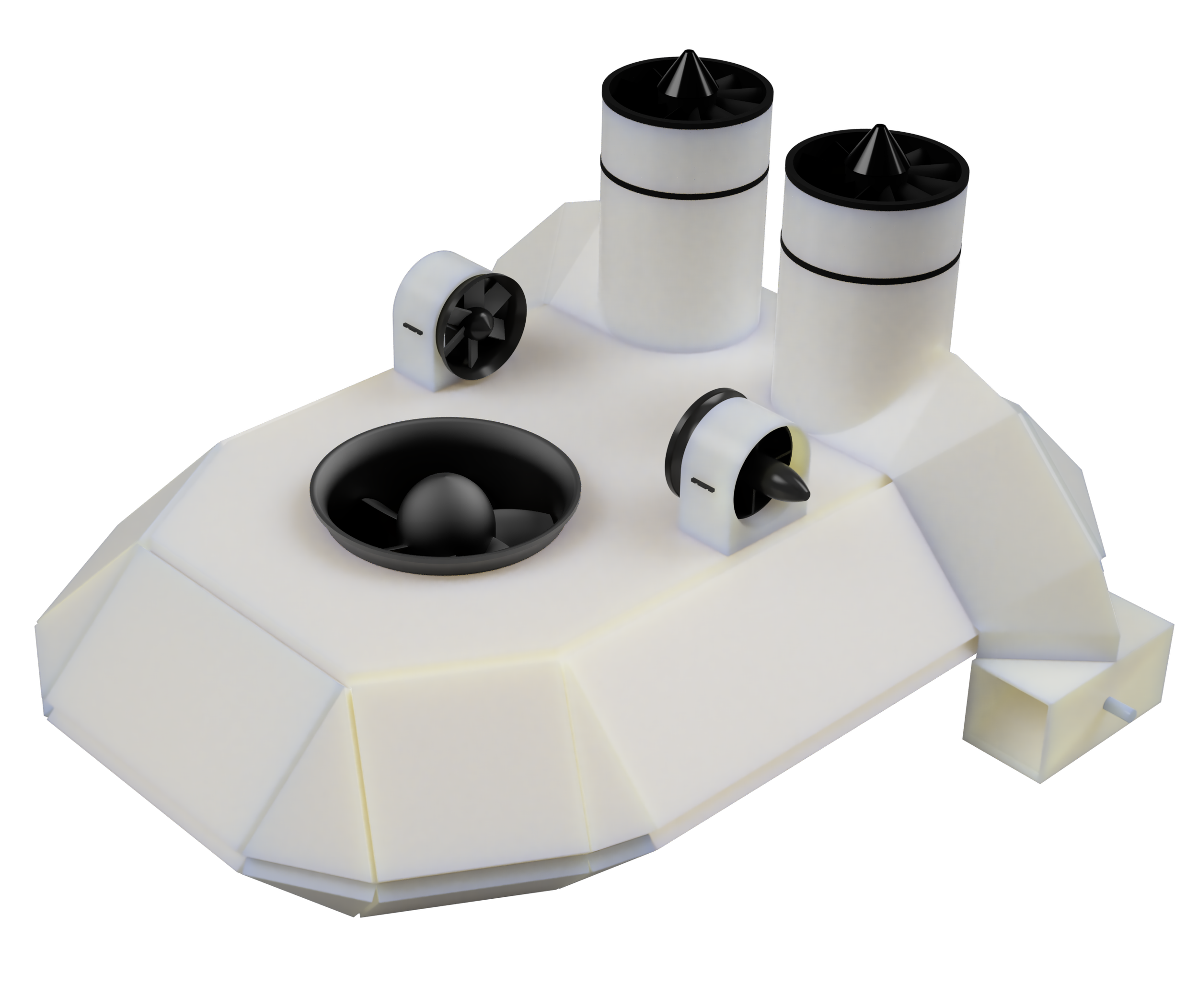
This design utilizes multiple sizes of electrical ducted fans (EDFs) to actuate the hovercraft in a decoupled manner. A 70 mm main lift EDF is used to provide static pressure and air flow for inflating the hovercraft's skirt. Its flow is ducted through the main body of the hovercraft to small slit openings on the underside of the craft. The air is then routed through the skirt into a central cavity created by the skirt's inflation. This air then finally leaves the hovercraft by passing under the fingers of the inflated skirt, allowing the hovercraft to float on both the skirt as well as a trapped cavity of air.
Two independent 30 mm EDFs are used for lateral control of the hovercraft's sway. These fans are centered on the chassis such that actuation of either fan creates thrust vectors that pass directly through the hovercraft's center of mass. This allows for pure sway control without any yaw effects, thus fully decoupling the sway actuation from the rest of the hovercraft's dynamics. Additionally, two independent 50 mm EDFs are mounted in ducted “towers” on the rear of the vehicle. The airflow from these fans is routed through ducting which passes through a valve allowing selection of the proportion of airflow going towards either the stern or bow of the vehicle. By changing the angle of the valve's paddle along with the speed of its respective EDF, surge and yaw can be controlled. Furthermore, due to the ducting of the valves, both forward and backward surge can be fully actuated upon.
This design thus allows for actuation in port sway, starboard sway, forward surge, backward surge, positive yaw, and negative yaw in a way such that each is allowed to be actuated independently of the rest of the hovercraft's dynamics. This design also only utilizes 4 movement fans to control 6 independent directions, reducing the total cost, weight, and complexity of the vehicle.
Using a simple PID controller, the pseudo-damping of the 6 directions can be implemented. Each direction uses the same damping controller, and the outputs of these controllers are then summed and processed by a vehicle dynamics algorithm in order to command the EDFs and servo motors appropriately to achieve the desired damping effect.

Section 4.0.0 <Simulation>
The surge velocity, \(\dot{u}\), was simulated as depicted in pink after an initial commanded movement. The simulated hovercraft was commanded backward for approximately 0.5 seconds before all external commands were halted. The damping controller then actuates the vehicle in the forward surge direction to bring the vehicle to zero velocity. Some overshoot can be seen as the vehicle experiences a slight amount of forward surge velocity, but this can be easily addressed through better tuning of the controller’s parameters. Nevertheless, this controller definitely smooths out the motion of the hovercraft and removes some of the “jerky” motion as described previously.
This scenario acts as a unit baseline for all other possible movements, as the controller adaptation and the damping forces can be linearly summed as commanded movements can be linearly summed, due to the decoupled independent nature of the hovercraft's control dynamics. Of course, given an actual adaptive controller which could adapt to the human operator’s piloting style, the decrease in trust due to the overshooting and undershooting of the assistive controller would gradually eventuate to zero as the controller learned the specific human operator's piloting style.
Depicted in blue is another simulation of the hovercraft’s movement. In this case, the hovercraft is already moving at the start of the simulation and it attempts to bring its velocity down to zero. Then, the hovercraft is linearly forced, which can be interpreted as it being “pushed” by an external factor, to a much greater velocity. This is seen as the “spike” in the graph, with its apex being when the force is halted. Again, it attempts to bring its velocity back to zero, with some considerable overshoot.


Section 5.0.0 <Conceptual Design>
Mechanical Design:
Chassis
1 cm thick foam board for chassis
Duct tape for joins
Seal joins with hot glue
Angular body panels for cooler look
Skirt
Fingerless skirt (Skirt with fingers for v2 maybe?)
Skirt made out of parachute fabric
Attached via sandwiched layer of chassis -> hot glue -> skirt -> hot glue (at cut ends of skirt) -> duct tape
Lifting power
Lifting fan laterally centered near the front of the vehicle
Lifting fan sunken into the chassis
Lifting fan is off-the-shelf EDF
Lifting fan has mesh on intake to prevent debris
Lifting fan has front “wind shield” for protection from larger debris
Movement power
2 thrust fans, one on either side of the chassis
Mounted on rear top sides of the chassis
Thrust fans are off-the-shelf EDFs (Smaller than lifting fan)
3D-printed ducting to redirect airflow
Thrust fans have mesh on intake to prevent debris
Ducting has both a front duct and a rear duct, for forwards and backwards movement
Thrust vector is controlled by a valve, which switches the ducting between front and back
Electrical Design:
Powered by Li-ion battery cell packs
Using braided cable sleeves with shielding, tied down to chassis, for external wiring
Using XT-60 connectors for DC power
Using banana plugs for AC power
Control Design:
Using NRF24L01 transceiver modules
Move-to-location controls via serial commands from a computer
Servo motors to control thrust duct valves
Section 5.1.0 <Prototype>
The initial prototype for the hovercraft was made out of foam board. This allowed for quick and easy modifications to be made to the main body structure of the vehicle. A skirt made of parachute material was then attached to the bottom of the craft, with the air first being routed into the skirt, then out into the void directly under the bottom of the hovercraft, when it’s hovering, and then out beneath the skirt.
The general design relies on 3 EDFs: Two to control surge and yaw, and one to inflate the skirt and allow for hovering. For the movement EDFs, they were mounted in “towers” and then ducted into a diverter mechanism which redirected the air either towards the front or the rear of the vehicle. Since this was done on both sides, this allowed for forwards and backwards movement, as well as a differential turning maneuver.


Section 5.2.0 <Prototype Fabrication>
After the initial design was completed, the more complex geometry of the prototype was cut up into pieces that allowed for ease of 3D printing, meaning part orientation was optimized to minimize the amount of support material needed, and to maximize the ease that the support material could be removed.


Section 6.0.0 <Functional Design>
Design goals:
Lighter
Smaller
More maneuverable
Less power consumption
Section 6.1.0 <Ver.0>
The initial functional version of the hovercraft was created out of 3D printed plates. The design kept many of the features introduced in the prototype, but now also added two small sway EDFs, turning this into a fully actuated vehicle in terms of a control system. This design also reduced the length and width of the craft as well as reduced the length of the surge ducts.


Section 7.0.0 <Controller Design>
A multi-function wireless controller was also designed to control the hovercraft. This was based on a Teensy microcontroller and an NRF24L01 wireless transceiver chip. The benefits of this controller over a standard controller are that it has double the number of joysticks, as well as a very large amount of analog controls. Additionally, the receiver side of the controller, since it would also be based on a programmable microcontroller, could have its control parameters easily modified to provide different control “feels”. This would allow for the changing of different setpoints, midpoints, and deadzones in each of the controller inputs. It would also allow for the implementation of the previously discussed PID controller for halting vehicle movement and making the craft much easier to control through the addition of a “faux friction”.
